
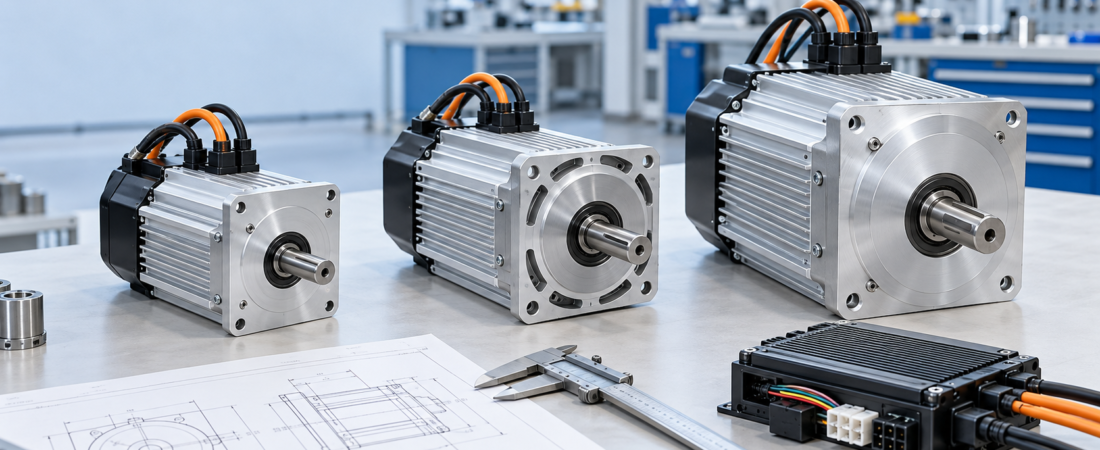
120 vs. 140 vs. 146 mm BLDC Motors: How OEMs Should Choose the Right Platform
Selecting a brushless DC motor for industrial equipment is not simply a matter of choosing the largest housing or the highest power rating. For OEM projects, the correct motor must fit the machine mechanically, match the battery and controller electrically, and deliver the required torque throughout the actual duty cycle.
HAGMOTOR supplies configurable 120, 140 and 146 mm-class BLDC motor platforms for agricultural machinery, material-handling equipment, utility vehicles, construction machines and other custom drive systems.
These platform names are useful starting points, but they should not be treated as complete installation dimensions. The final outline, flange, shaft, cable direction and mounting pattern must always be confirmed using the correct technical drawing.
Start With the Machine, Not the Motor Diameter
Before comparing motor platforms, define what the machine must do.
The most useful project information includes:
- Machine type and application
- Battery nominal and maximum voltage
- Required continuous operating speed
- Required starting and working torque
- Maximum short-duration load
- Duty cycle and operating time
- Available installation space
- Shaft or transmission connection
- Ambient temperature and working environment
- Controller functions and communication requirements
A compact machine with limited installation space may require a smaller motor platform with a carefully selected reduction ratio. A heavier machine may need a larger mounting interface or a motor capable of handling higher continuous thermal loads.
The motor diameter is therefore only one part of the decision.
Understanding the Three Motor Platforms
120 mm-Class Platform
A 120 mm-class BLDC motor is generally considered when installation space and total drive-system size are tightly controlled.
Potential applications include compact agricultural equipment, sprayers, grinding machines, smaller utility equipment and specialized mobile machinery.
During selection, engineers should pay particular attention to continuous torque, cooling conditions and transmission ratio. A physically compact motor may meet the speed requirement but still overheat if it must continuously operate near its short-duration torque limit.
140 mm-Class Platform
The 140 mm-class platform can provide a useful balance between installation size, mechanical interface options and configurable output.
It may be considered for pallet trucks, industrial machinery, agricultural machines, electric tricycles and other equipment requiring a more substantial drive package.
However, two motors described as “140 mm” may still have different flange patterns, overall lengths, shaft structures and cable positions. A dimensional drawing should be reviewed before prototypes or mounting brackets are produced.
146 mm-Class Platform
A 146 mm-class motor may be selected when the equipment uses a corresponding mounting structure, reinforced flange or specialized output connection.
This platform can be relevant to engineering vehicles, industrial drivetrains and machinery requiring a robust mechanical interface.
It should not automatically be assumed to deliver more usable torque than every smaller motor. Usable performance still depends on winding configuration, controller current, speed, thermal design, reduction ratio and duty cycle.
Seven Compatibility Checks Before Ordering
1. Mounting Interface
Confirm the flange diameter, pilot position, bolt-hole pattern, mounting-hole size and available installation depth.
The motor should be located by the intended machined reference surface—not only by its bolts. Incorrect positioning can cause shaft misalignment, vibration, bearing stress and premature transmission wear.
2. Shaft and Output Connection
Specify whether the machine requires:
- Smooth shaft
- Keyway shaft
- External spline
- Internal or hollow spline
- Threaded end
- Sprocket or coupling connection
- Custom gearbox interface
Provide the shaft diameter, effective length, spline details, key dimensions and required rotation direction. A photograph alone is usually insufficient for accurate OEM matching.
3. Rated and Peak Torque
Rated torque and peak torque serve different purposes.
Rated torque is the torque the motor is designed to provide continuously under specified cooling and operating conditions. Peak torque is normally available only for acceleration, starting or short overload periods.
Mechanical output can be estimated using:
Torque (N·m) = 9550 × Power (kW) ÷ Speed (rpm)
This calculation is useful for checking whether a proposed power and speed combination is reasonable. It does not replace a complete review of starting load, gradients, acceleration, transmission losses and duty cycle.
4. Motor Speed and Transmission Ratio
Do not choose motor rpm without considering the gearbox, sprocket, wheel or driven mechanism.
A motor operating at a more suitable speed with the correct reduction ratio may perform better than a low-speed motor connected directly to the load. The transmission should allow the motor to work efficiently during normal operation while still delivering enough wheel or shaft torque at startup.
5. Battery Voltage Range
The motor, controller and battery must be evaluated as one system.
Check:
- Battery nominal voltage
- Fully charged voltage
- Low-voltage cutoff
- Voltage drop under load
- Regenerative voltage, if applicable
- Controller operating-voltage range
A “60 V” battery system does not remain at exactly 60 V throughout operation. The controller must tolerate the battery’s real voltage range.
6. Controller and Feedback Compatibility
Confirm the controller’s continuous and peak current limits, Hall-sensor arrangement, phase sequence, throttle input and required functions.
Possible functions include:
- Forward and reverse
- Variable-speed control
- Electric braking
- Regenerative braking
- Low-speed mode
- Temperature protection
- Speed output
- CAN communication
A controller with a high advertised current rating is not automatically suitable. Its current-control strategy, voltage range, feedback type and wiring must match the motor.
7. Wiring and Thermal Management
Specify cable length, terminal type, connector model, cable exit direction and environmental sealing requirements.
The installation must also allow heat to leave the motor. Avoid enclosing the motor in an unventilated compartment unless the complete thermal system has been evaluated.
High current, low operating speed, frequent starting and repeated overloads can all increase motor temperature.
A Practical OEM Selection Workflow
A reliable selection process can follow five steps:
- Define the machine load, target speed and operating cycle.
- Calculate the required output torque and transmission ratio.
- Compare the available installation space with motor drawings.
- Match the motor, controller, battery and wiring configuration.
- Test a sample under representative working conditions before batch production.
During testing, record motor temperature, controller temperature, battery voltage, operating current, acceleration and performance under the heaviest normal load.
The commonly referenced JWH 60V–1000W configuration should be treated only as an illustrative starting point unless its specifications have been confirmed for the actual product and application.
Common Selection Mistakes
OEM projects often encounter problems when buyers:
- Choose only by motor diameter or power label
- Compare peak torque with another motor’s rated torque
- Ignore the fully charged battery voltage
- Confirm the motor before checking the shaft drawing
- Use an unmatched controller
- Install cables where they interfere with the frame
- Test without the real transmission or operating load
- Assume one reference model suits every application
Reviewing these details before production can reduce bracket changes, wiring revisions and repeated sample development.
FAQ
Is a 146 mm motor always more powerful than a 140 mm motor?
No. Frame size alone does not determine power or torque. Compare winding design, rated speed, continuous current, controller settings, cooling and duty cycle.
Can the same controller operate different motor platforms?
Sometimes, but compatibility must be confirmed. Voltage, current, Hall signals, phase sequence, temperature sensors and control functions must match.
What drawing information should an OEM provide?
Provide mounting dimensions, shaft or spline details, available space, cable direction, transmission arrangement and the machine’s mechanical load requirements.
Can HAGMOTOR customize the output shaft and wiring?
Custom shaft, flange, cable, connector and controller configurations can be discussed according to the project drawing and order requirements.
Request a Motor Recommendation
Choosing between 120, 140 and 146 mm motor platforms requires more than comparing catalog labels.
Send HAGMOTOR your machine application, battery voltage, target speed, required torque, duty cycle, mounting drawing, shaft specification and estimated quantity. Our team can review the mechanical and electrical interfaces for your project.
Contact HAGMOTOR: https://hagmotor.com/
SEO keywords
- 120 mm BLDC motor
- 140 mm brushless DC motor
- 146 mm BLDC motor
- OEM motor selection
- Custom industrial motor
20-second video shot list
- 0–4 seconds: Three motor platforms arranged from compact to larger frame size.
- 4–8 seconds: Caliper measuring the mounting flange and pilot diameter.
- 8–12 seconds: Close-up of smooth shaft, spline and flange interfaces.
- 12–16 seconds: Controller, phase cables and signal connector being matched.
- 16–20 seconds: Complete motor-controller system beside the machine installation drawing.
Video caption:
Motor size is only the starting point. Match the mounting, shaft, torque, speed, controller and wiring before selecting your OEM BLDC drive system. Learn more at HAGMOTOR.com.