
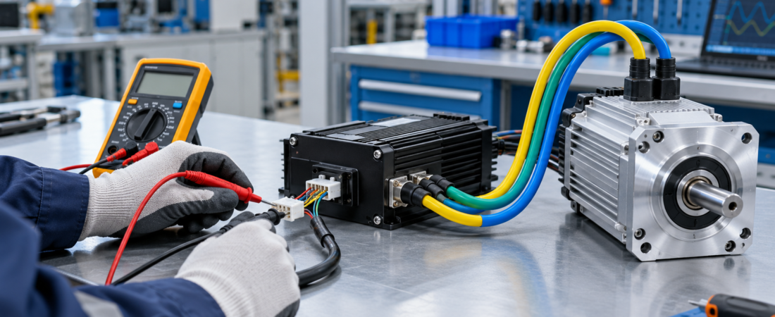
A brushless DC motor that vibrates, runs backward, starts intermittently or draws high current is not necessarily defective. In many OEM installations, these symptoms are caused by an incorrect phase-wire sequence, an incompatible Hall-sensor arrangement, a controller setting or excessive mechanical resistance.
Replacing the motor before checking the complete drive system can waste time and may leave the original problem unresolved.
This guide provides equipment manufacturers and service engineers with a structured method for checking a sensored BLDC motor system. It applies to industrial machinery, electric tricycles, agricultural equipment, pallet trucks, utility vehicles and other low-voltage drive applications.
Safety Before Troubleshooting
Disconnect the battery or DC power source before touching connectors, changing wires or performing resistance measurements.
Also follow these precautions:
- Secure the machine against unexpected movement.
- Lift drive wheels only with approved supports when a no-load rotation test is required.
- Remove chains, belts or couplings when practical.
- Do not disconnect power cables while the controller is energized.
- Do not short phase wires or battery terminals.
- Use test equipment rated for the system voltage.
- Follow the controller manufacturer’s wiring diagram.
- Allow charged controller capacitors to discharge before handling terminals.
Powered signal tests should only be performed by qualified personnel familiar with the system.
How Phase Wires and Hall Sensors Work Together
A typical sensored three-phase BLDC motor has three heavy phase conductors and a smaller feedback connector.
The phase wires carry current from the controller to the motor windings. The Hall sensors report rotor position so the controller knows which phases to energize.
For smooth commutation, three elements must agree:
- The motor’s phase sequence
- The Hall-sensor sequence
- The controller’s commutation logic
Cable colors are helpful, but they are not a universal standard. A yellow motor phase wire does not always correspond to a yellow controller wire from another manufacturer.
Connecting colors directly without checking the motor and controller documentation can produce rough starting, reverse rotation or excessive current.
Common Symptoms and Likely Causes
Motor Shakes but Does Not Rotate
Possible causes include:
- One phase connection is open
- A Hall signal is missing
- Phase and Hall sequences do not match
- Battery voltage falls sharply during startup
- Controller startup current is restricted
- Brake or interlock input remains active
- The driven mechanism is jammed
Do not repeatedly apply full throttle. Incorrect commutation can create high current while producing very little useful torque.
Motor Starts Roughly or Makes Abnormal Noise
Check for a loose phase terminal, damaged connector pin, incorrect Hall sequence or controller timing incompatibility.
Also inspect the mechanical installation. A misaligned coupling, tight bearing, incorrect chain tension or gearbox problem can create symptoms similar to an electrical fault.
Motor Rotates in the Wrong Direction
First check whether the controller has a dedicated forward/reverse input or software direction setting.
Some controllers permit direction changes through configuration. Others require a specific phase-and-Hall sequence. Randomly exchanging only two phase wires may reverse a sensorless motor, but on a sensored system it can also create an incorrect commutation combination.
Follow the approved wiring combination for the motor-controller pair.
Motor Runs Without Load but Stops Under Load
This can indicate:
- Battery voltage sag
- Controller current limiting
- Insufficient starting torque
- Incorrect transmission ratio
- Excessive mechanical resistance
- Poor phase connection
- A motor selected by peak rather than rated performance
Rated torque is intended for continuous operation under specified conditions. Peak torque is normally available only for starting, acceleration or short overload events.
Step-by-Step Diagnostic Process
Step 1: Confirm Basic System Compatibility
Before testing individual wires, verify that the major components belong together.
Confirm:
- Battery nominal and fully charged voltage
- Controller operating-voltage range
- Motor rated-voltage range
- Controller continuous and peak current limits
- Motor rated and peak-current requirements
- Hall-sensor supply voltage
- Throttle or command-signal type
- Brake, reverse and interlock inputs
Power, rpm and torque must also suit the transmission and machine load. A correctly wired motor can still perform poorly if the selected speed or gear ratio is unsuitable.
Any JWH 60V–1000W reference configuration should be treated as an illustrative model only until the actual motor, controller and application specifications are confirmed.
Step 2: Perform a Visual Inspection
With the system isolated, inspect:
- Loose or discolored phase terminals
- Pins pushed backward inside connectors
- Damaged insulation
- Incorrectly crimped terminals
- Water or contamination inside connectors
- Cables pulled tightly against the frame
- Hall wires installed in the wrong connector positions
- Missing ground or shield connections where required
A terminal may look connected while making poor contact under current. Gently check each crimp and connector lock.
Step 3: Check the Three Motor Phases
Disconnect the motor from the controller before resistance or continuity testing.
Measure resistance between each phase pair:
- Phase U to V
- Phase V to W
- Phase W to U
The three readings should be reasonably consistent for the same motor and test conditions. Very low winding resistance can be difficult to measure accurately with a standard handheld meter, so the comparison between pairs is often more useful than the absolute reading.
Also check that the phase conductors are not shorted to the motor housing. Interpret the result according to the motor design and manufacturer’s procedure.
A significantly different phase-to-phase result may indicate a damaged winding, cable or connection.
Step 4: Check Hall-Sensor Supply and Ground
Hall sensors commonly use a low-voltage supply, but the exact value must be confirmed from the motor and controller documentation.
Verify the connector pinout before energizing it. Applying battery voltage to a Hall-sensor wire can immediately damage the sensors.
With the correct low-voltage supply present, confirm:
- Hall supply voltage
- Hall ground continuity
- Secure connector pins
- No short between signal and power conductors
Step 5: Verify Hall-Signal Switching
When tested according to the approved procedure, each Hall signal should change state as the rotor turns slowly.
If one signal remains permanently high or low, investigate:
- Damaged Hall sensor
- Broken signal wire
- Poor connector contact
- Incorrect supply or ground
- Wrong pin assignment
All three signals must form the sequence expected by the controller. Individual sensors can switch correctly while the overall sequence remains incompatible.
Step 6: Confirm the Phase-and-Hall Combination
Use the motor manufacturer’s wiring table or a known approved motor-controller combination whenever possible.
If no confirmed table exists, systematic matching should be carried out by qualified technicians using limited current and controlled no-load testing. Record each connection rather than changing several wires randomly.
A valid combination should provide:
- Smooth startup
- Correct direction
- Low no-load current
- Minimal vibration
- Consistent acceleration
- No abnormal controller or motor heating
Correct rotation alone does not prove that the commutation combination is efficient.
Step 7: Separate Electrical and Mechanical Problems
Disconnect the motor from the driven mechanism when practical and rotate both sides by hand.
Check for:
- Tight bearings
- Misaligned shafts
- Bent couplings
- Excessive chain tension
- Gearbox resistance
- Brake drag
- Obstructions in the machine
If the motor operates normally without the transmission attached, the main problem may be mechanical or related to the reduction ratio rather than wiring.
Checks Before OEM Batch Production
Before approving a motor-controller system for production, test it under representative conditions.
Record:
- Battery voltage at rest and under load
- No-load current
- Loaded operating current
- Starting behavior
- Motor and controller temperature
- Rated operating speed
- Acceleration and braking
- Forward and reverse operation
- Cable and connector temperature
- Performance during the intended duty cycle
Document the final phase connections, Hall pinout, connector model, controller settings and rotation direction. A controlled wiring specification prevents assembly errors when production quantities increase.
FAQ
Can I identify phase and Hall wires only by color?
No. Wire colors are not universal across different manufacturers. Use the confirmed pinout or wiring diagram.
Will swapping two phase wires safely reverse every BLDC motor?
No. Sensored systems require the phase sequence and Hall sequence to remain compatible. Use the controller’s reverse function or an approved wiring combination.
Why does the motor rotate but draw unusually high current?
The motor may be operating with an inefficient commutation combination, excessive mechanical load, incorrect timing or an unsuitable transmission ratio.
Can one controller work with several HAGMOTOR models?
Potentially, but voltage, current, Hall sequence, feedback signals, rpm range and required functions must be verified for each motor.
Request Technical Matching Support
For a new or existing drive system, send HAGMOTOR the motor model, controller information, battery voltage, wiring diagram, required rotation direction, target rpm, rated and peak torque requirements, mounting drawing and machine application.
HAGMOTOR can review the motor, controller, wiring and mechanical interface as one coordinated system.
Contact HAGMOTOR: https://hagmotor.com/