
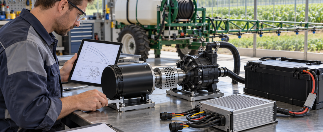
How to Match a BLDC Motor, Pump and Controller for an Agricultural Sprayer
An agricultural sprayer motor must do more than rotate a pump. It must produce the required flow and pressure, start reliably, operate within its thermal limits and remain compatible with the battery, controller and mechanical installation.
Selecting a motor from voltage and wattage alone can lead to poor pressure, excessive current, repeated controller faults or overheating.
A better process begins with the spray system’s hydraulic requirement and works backward toward the motor and electrical system.
Begin with the required flow and pressure
The first specification should be the pump’s operating point, sometimes called the duty point.
Determine:
- Required total flow
- Target working pressure
- Number and type of nozzles
- Pressure loss through hoses, valves and filters
- Whether agitation or bypass flow is required
- Maximum operating condition
- Expected liquid viscosity
- Whether the pump runs continuously or intermittently
The pump supplier should provide a performance curve showing flow, pressure, speed and required shaft power.
Do not select the motor only from the pump’s maximum advertised flow. A pump can deliver very different flow depending on its speed and the resistance of the complete system.
Determine the pump speed
Once the required operating point is known, identify the pump speed needed to produce that flow and pressure.
For many rotodynamic pumps, flow, pressure and power change significantly with speed. Grundfos explains that variable-speed operation can control flow and pressure while avoiding some of the energy loss associated with throttling a fixed-speed pump. Grundfos
However, pump affinity laws should not be treated as a substitute for the actual pump curve. Positive-displacement diaphragm, piston and gear pumps behave differently from centrifugal pumps.
Always use data for the exact pump design.
Convert the pump requirement into motor torque
The motor must provide sufficient torque at the required operating speed.
Mechanical output power can be expressed as:\[ P=\frac{2\pi nT}{60} \]
Where:
- \(P\) is mechanical power in watts
- \(n\) is rotational speed in rpm
- \(T\) is torque in newton-metres
This relationship helps explain why two motors with the same power rating may behave differently. One may be designed for higher speed and lower torque, while another produces more torque at a lower speed.
The pump may also require additional starting torque when the system is pressurized, the liquid is cold or mechanical friction is high.
Separate continuous and peak requirements
A sprayer may require high torque for a few seconds during startup and a lower torque while running steadily.
These values should be listed separately:
| Requirement | Meaning |
|---|---|
| Rated speed | Normal continuous operating speed |
| Rated torque | Torque the motor can provide continuously under specified cooling conditions |
| Peak torque | Short-duration torque available for starting or temporary load changes |
| Rated current | Continuous current under the defined operating condition |
| Peak current | Temporary current required during acceleration or overload |
| Duty cycle | Ratio of running time to rest time |
| Ambient temperature | Air temperature around the installed motor |
Peak torque is not continuous torque. A motor capable of a large short-duration peak may still overheat if the normal pump load exceeds its continuous rating.
In brush and brushless DC motors, motor current is closely related to torque. A current-controlled drive therefore uses current as part of the torque-control process. maxon group
Confirm the battery voltage range
The battery’s nominal voltage is only the starting point.
The motor and controller must tolerate the complete battery range:
- Voltage immediately after charging
- Normal operating voltage
- Low-voltage condition
- Voltage drop during pump startup
- Regenerative or transient voltage, if applicable
A motor advertised as “60V” should not automatically be connected to any battery or controller carrying the same nominal label.
The system supplier must confirm the allowable motor and controller voltage ranges, battery chemistry, current capability and low-voltage protection.
The previously used JWH 60V–1000W specification is an illustrative product reference only. It should not be treated as a universal recommendation for every sprayer.
Match the controller to the motor and pump load
The controller must be compatible with:
- Battery-voltage range
- Motor phase current
- Continuous and peak current demand
- Hall-sensor or sensorless operation
- Motor pole configuration
- Speed-control input
- Direction command
- Temperature feedback, where provided
- Required protection strategy
- Wiring and connector arrangement
Battery current and motor phase current are not always the same. A controller may draw one current from the battery while producing a different phase-current waveform inside the motor.
For this reason, controller selection should use the manufacturer’s continuous and peak ratings under the actual cooling and installation conditions.
Sensored or sensorless control?
Many BLDC motors use Hall sensors to report rotor position. Microchip describes a common sensored BLDC arrangement using three Hall-effect sensors positioned around the motor. developerhelp.microchip.com
Hall-sensored control can be useful when the application needs:
- Reliable starting under load
- Controlled low-speed operation
- Predictable commutation during startup
- Direction control at low speed
Sensorless control may simplify the wiring but can be less suitable for some low-speed or loaded-start conditions. The correct choice depends on the control method, pump starting load and expected speed range.
Do not exchange motor or controller wiring diagrams based only on wire colors. Phase wires, Hall signals, power, ground and temperature-sensor leads must be confirmed from the actual documentation.
Check the mechanical interface
Electrical compatibility does not solve a mechanical mismatch.
Confirm:
- Shaft diameter and length
- Keyway, spline or threaded end
- Rotation direction
- Motor flange or mounting-foot pattern
- Coupling type
- Pump-shaft height
- Alignment tolerance
- Allowable radial and axial load
- Available installation space
- Protection from water, chemicals and dust
A rigidly misaligned coupling can increase bearing load, vibration and power consumption. The motor and pump shafts should be aligned according to the coupling and equipment instructions.
If a belt drive or gearbox is used, include its ratio, efficiency and external shaft loads when selecting the motor.
Consider cooling and installation
A motor’s continuous rating depends partly on how heat leaves the motor.
An enclosed compartment, high ambient temperature, chemical deposits or blocked airflow can reduce the available continuous output. Mounting the motor to a metal frame may improve heat transfer, but this must be evaluated for the real installation.
Do not assume that an IP rating, insulation class or temperature limit applies unless it is confirmed for the exact motor being supplied.
Estimate battery capacity from the duty cycle
Battery capacity should be based on average electrical demand and required operating time, with allowances for:
- Pump-load variation
- Controller and motor losses
- Battery usable-energy limits
- Temperature
- Battery aging
- Wiring voltage drop
- Required operating reserve
A simple amp-hour calculation based only on the motor’s maximum current often gives an unrealistic result. Measure or estimate the complete working cycle: spraying, turning, pressure adjustment, idling and rest periods.
The charger must match the battery chemistry and voltage. Battery charging and maintenance should follow the actual battery and charger manuals.
Test the complete system
Before production release, test the motor, pump, controller and battery together.
Record:
- Pump flow and pressure
- Motor speed
- Battery current
- Controller phase current, where available
- Motor and controller temperature
- Battery-voltage drop during startup
- Startup time
- Noise and vibration
- Controller fault history
- Performance after continuous operation
Testing should cover the normal condition and the most demanding approved operating condition. Protective functions should not be bypassed during testing.
Common selection mistakes
Avoid these frequent problems:
- Choosing a motor from wattage alone
- Using maximum pump flow instead of the real duty point
- Confusing peak torque with continuous torque
- Ignoring pressure losses in hoses and filters
- Assuming identical nominal voltage means compatibility
- Selecting the controller from battery current alone
- Reversing Hall or phase wiring without documentation
- Ignoring shaft and mounting dimensions
- Testing only with water when the real liquid behaves differently
- Evaluating temperature after only a brief no-load test
FAQ
Is a 1,000W BLDC motor enough for an agricultural sprayer?
The power figure alone cannot answer this. Required flow, pressure, pump efficiency, operating speed, continuous torque and duty cycle must be confirmed.
Should a sprayer pump use a Hall-sensored motor?
Hall sensors may improve starting and low-speed control in some loaded applications. The decision must match the controller and pump behavior.
Can motor speed be reduced to adjust spray flow?
It may be possible when the pump type and controller support variable-speed operation. Verify the pump curve and minimum operating requirements.
Can the controller have a higher current rating than the motor?
A higher controller rating does not mean the system should deliver that current continuously. Current limits must be configured to protect the motor and match the application.
What information should an OEM send to HAGMOTOR?
Send the pump curve, required flow and pressure, target rpm, continuous and peak torque, battery-voltage range, duty cycle, shaft drawing, mounting dimensions, controller requirements and operating environment.
Conclusion
A reliable agricultural sprayer drive begins with the hydraulic duty point and finishes with complete mechanical and electrical verification.
HAGMOTOR can evaluate the required torque, speed, voltage, controller, shaft and mounting interface for application-specific BLDC motor solutions.
Discuss your agricultural machinery project: https://hagmotor.com/