
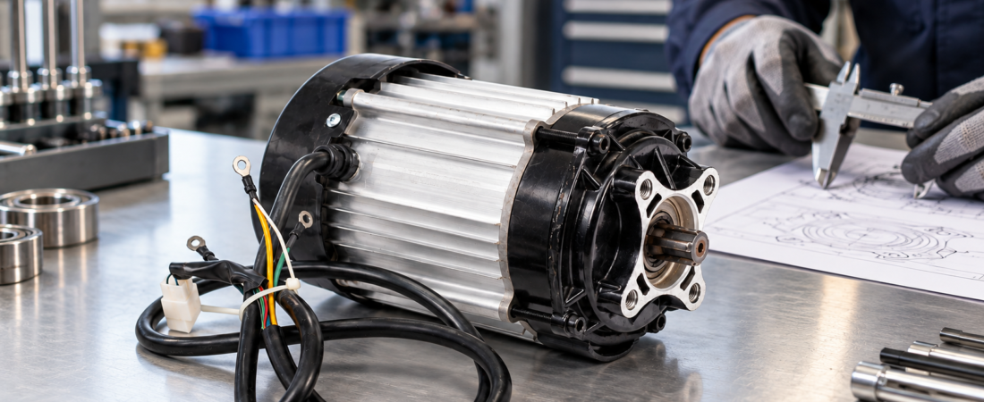
A motor can look like the right replacement and still fail during installation. The shaft may fit the coupling but sit at the wrong depth. The mounting holes may align while the cable exits into a machine panel. Or the motor may be suitable for the load, yet incompatible with the existing controller.
For an OEM replacing a brushless DC (BLDC) motor in industrial machinery, the useful starting point is a record of the machine, motor and controller as one drive system. Collect the details below before requesting a replacement or custom design.
1. Record the machine’s actual work cycle
Begin with what the machine drives: a conveyor, pump, polishing head, grinding mechanism or another rotating load. Note the required output speed, how quickly it must accelerate, how often it starts and stops, and how long it runs under load.
The motor must provide enough torque at the required operating speed, as well as enough acceleration torque for the connected load’s inertia. A short period of high torque does not establish that the motor can sustain that torque throughout a shift. Motor sizing therefore considers speed, load torque, acceleration and inertia together. Oriental Motor’s motor-sizing guide explains this selection approach. orientalmotor.com
Ask the maintenance or design team for the existing duty cycle and any measured load data. If those are unavailable, describe the machine’s operating sequence rather than guessing a required wattage.
2. Separate rated performance from peak performance
When comparing candidate motors, request rated voltage, rated mechanical output power, rated speed and rated torque at the same operating point. Also request the conditions under which those ratings apply, including cooling and operating duration.
Peak torque is a separate, limited-duration value. It may help during startup or a brief load increase, but it should not be used as the continuous-load rating. A controller’s current limit and the available power supply can also restrict the torque the installed system actually delivers.
As a basic cross-check, mechanical output power is approximately:
Power (kW) = Torque (N·m) × Speed (rpm) ÷ 9,550
This equation helps reveal inconsistent figures in a proposed operating point. It does not establish motor efficiency, temperature rise or suitability for a particular duty cycle. Request the supplier’s confirmed performance information for the proposed motor and controller combination.
3. Measure the complete mechanical interface
A front-view photograph is useful, but it cannot establish fit. Prepare a dimensioned drawing or measure the removed motor after the equipment has been made safe for service. Record:
- Overall body length and diameter, including covers and cable exit
- Mounting type, hole pattern, pilot diameter and available clearance
- Shaft diameter, protruding length, spline, keyway or thread
- Coupling or pulley position and the required direction of rotation
- Cable exit direction and the space needed to route the harness
Check how the driven component is supported. A pulley or other load that applies force across the shaft can create bearing demands that differ from a direct-coupled installation. Do not assume that a shaft with a matching diameter has the same bearing arrangement or permitted loading.
Keep photographs of the machine-side mount, coupling and existing nameplate with the drawing. They allow the motor supplier to identify conflicts before a sample is built.
4. Match the supply and controller
“BLDC motor” does not mean “works with any BLDC controller.” Confirm the machine’s supply-voltage range under real operating conditions, along with the controller’s voltage range and current settings. For a battery-powered machine, include the battery’s operating range and relevant protection behavior. For a rectified or regulated DC supply, provide its actual output and current capability.
Then identify the controller’s commutation and feedback requirements. A sensored system may need compatible Hall-sensor supply voltage, signal type, connector pinout and phase-to-sensor relationship. A sensorless system uses a different way to determine rotor position; its behavior at startup and low speed must be checked against the application. Texas Instruments describes both approaches in its BLDC commutation application brief. TI.com
Document every connector and wire by function and verified pinout. Wire colors visible in a photograph are not a wiring diagram. Include the required speed command, enable input, direction command, braking behavior and fault output when applicable.
5. Check the installation environment
Describe where the motor sits: inside an enclosure, near process dust, beside washdown equipment or in a space with restricted airflow. Include ambient temperature, likely contamination and the mounting orientation. These details affect the housing, sealing, cable routing and cooling arrangement selected for the application.
For grinding and sharpening machinery, motor replacement is only one part of the equipment review. The machine builder must verify the abrasive wheel’s permitted speed, mounting and guarding against the wheel manufacturer’s instructions and applicable local requirements. In the United States, OSHA’s abrasive-wheel machinery rule addresses guarding and mounting for covered equipment; applicability depends on the machine and jurisdiction. Occupational Safety and Health Administration
During removal and installation, follow the equipment’s energy-isolation procedure and account for stored energy. OSHA’s control-of-hazardous-energy rule describes requirements for covered servicing work in the United States. Occupational Safety and Health Administration
6. Request a matched sample and validate it in the machine
Once the proposed motor, shaft and controller are defined, agree on a sample configuration and its drawing. A practical evaluation checks that the motor mounts without interference; the shaft and coupling align; the harness reaches without strain; and the controller responds correctly to start, stop, speed, direction and fault commands.
Next, evaluate the sample under the machine’s representative load and operating cycle. Record speed, current, temperature behavior and any controller faults using the test procedure appropriate to the equipment. Confirm acceptance criteria with the supplier before testing. A successful no-load spin shows basic operation, but it does not validate loaded performance.
HAGMOTOR lists configurable motor, shaft, mounting, controller and wiring interfaces for its industrial machinery range. The configuration and its actual ratings should be confirmed for the specific project; a photograph or another model’s data sheet is insufficient. View the industrial machinery motor page. hagmotor
Information to send with your inquiry
For a faster technical review, send the machine application, supply-voltage range, required speed and load data, operating cycle, existing motor and controller details, mechanical drawings, connector pinout, environmental conditions and expected quantity. Mark any unknown item clearly so it can be resolved during selection.
FAQ
Can I replace a BLDC motor with one that has the same rated power?
Rated power alone is insufficient. Compare torque at the working speed, duty cycle, shaft, mounting, voltage and controller compatibility.
Can I reuse the original controller?
Possibly. Its voltage and current limits, control method, feedback interface and wiring must be verified against the replacement motor.
Does a matching flange guarantee a drop-in installation?
No. Check the pilot, shaft engagement, coupling alignment, overall clearance and cable exit as well.
Need an industrial BLDC motor matched to your equipment? Send your machine requirements, drawings and controller details to HAGMOTOR for a project-specific review.