
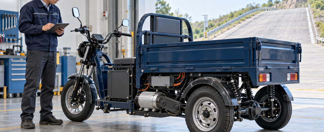
How to Select a BLDC Motor and Gear Ratio for an Electric Cargo Tricycle
An electric cargo tricycle that performs well on level roads may slow dramatically, overheat or trigger controller protection when climbing with a full load.
The usual response is to specify a higher-wattage motor. However, rated power alone does not determine hill-climbing performance. The vehicle also needs sufficient wheel torque, an appropriate reduction ratio, adequate controller current and a battery that can maintain voltage under load.
A reliable selection process begins with the loaded vehicle and its operating route—not with a motor label.
Define the Real Operating Condition
Before selecting a motor, collect the following information:
- Vehicle curb mass
- Maximum cargo and rider mass
- Wheel rolling radius
- Target maximum road speed
- Required climbing speed
- Steepest continuous gradient
- Length of the climb
- Number of hill starts per working cycle
- Road surface and tire condition
- Ambient temperature
- Daily operating time
- Available battery-voltage range
Use the maximum expected operating mass, not only the empty vehicle weight.
A short ramp approached at speed creates a different requirement from a long hill where the vehicle must start from rest and climb continuously.
Convert the Road Requirement into Wheel Torque
The motor must generate enough tractive force to overcome gradient resistance, rolling resistance and any required acceleration.
A simplified preliminary calculation may use:\[ F_{\text{grade}}=mg\sin\theta \]
Where:
- \(m\) is the total loaded mass
- \(g\) is gravitational acceleration
- \(\theta\) is the road angle
Rolling resistance and acceleration force must then be added. Aerodynamic drag may also matter at higher speeds, although it is often less important during low-speed climbing.
MathWorks’ longitudinal-vehicle model similarly treats road grade, tire rolling resistance and longitudinal tire force as separate contributors to vehicle motion. MATLAB
The required wheel torque is approximately:\[ T_{\text{wheel}}=F_{\text{total}}\times r_{\text{wheel}} \]
This is a preliminary engineering calculation. Tire traction, drivetrain losses, load transfer, surface conditions and component limits still need to be evaluated in the complete vehicle.
Match Motor Speed to Vehicle Speed
The wheel speed required for a target vehicle speed can be estimated from:\[ n_{\text{wheel}}=\frac{v\times60}{2\pi r_{\text{wheel}}} \]
Where:
- \(n_{\text{wheel}}\) is wheel speed in rpm
- \(v\) is vehicle speed in metres per second
- \(r_{\text{wheel}}\) is rolling radius in metres
The required overall reduction ratio is then related to motor speed and wheel speed:\[ i=\frac{n_{\text{motor}}}{n_{\text{wheel}}} \]
A higher numerical reduction ratio normally increases available wheel torque while reducing vehicle speed. A lower ratio may support a higher top speed but can leave the motor operating at excessive current during loaded starts or climbs.
Oriental Motor’s engineering guidance expresses the same basic relationship: gearhead output speed is motor speed divided by the reduction ratio, while output torque depends on motor torque, ratio and transmission efficiency. blog.orientalmotor.com
Do not select the ratio by top speed alone. Confirm that the motor can operate efficiently at the expected climbing speed as well.
Separate Rated and Peak Requirements
Electric tricycle specifications should distinguish between continuous and short-duration performance.
Rated values
Rated power and rated torque describe continuous operation under specified voltage, speed, cooling and ambient conditions.
They should support demanding conditions that last for meaningful periods, such as:
- Repeated delivery routes
- Long gradients
- Continuous low-speed operation
- Heavy cargo transport
- Hot-weather operation
Peak values
Peak torque and peak current may support:
- Initial acceleration
- Starting on a gradient
- Brief obstacles
- Short changes in road resistance
Peak performance is time-limited. A controller capable of high short-term current does not make the motor’s peak torque available continuously.
If a tricycle climbs slowly for several minutes, the application must be evaluated against the continuous thermal capability of the motor, controller and transmission—not only their peak figures.
Select the Motor and Reduction Drive Together
A preliminary relationship between motor torque and wheel torque is:\[ T_{\text{wheel}}\approx T_{\text{motor}}\times i\times\eta \]
Where \(\eta\) represents the combined efficiency of the gearbox, chain, belt, differential and bearings.
Actual efficiency should come from the selected drivetrain supplier. It should not be replaced with an assumed universal value.
When comparing motor options, confirm:
- Rated and peak torque
- Rated and maximum rpm
- Rated and peak mechanical power
- Motor efficiency map, where available
- Permitted operating duration at peak torque
- Cooling method
- Rotation direction
- Shaft and bearing limits
A motor that is too lightly geared may draw high current at low speed. Excessively high reduction can unnecessarily limit road speed and increase motor rpm at normal travel speed.
Match the Controller to the Traction Load
The controller must be compatible with the motor’s electrical design and the battery’s complete operating-voltage range.
Confirm:
- Minimum and maximum battery voltage
- Continuous and peak phase current
- Continuous and peak battery current
- Motor commutation method
- Hall-sensor arrangement
- Throttle or accelerator input
- Forward and reverse commands
- Brake and parking interlocks
- Speed feedback
- Motor-temperature input, if provided
- Low-voltage, overcurrent and thermal protection
- Connector and pin assignments
Motor phase current and battery current are not necessarily equal, so the two ratings should not be used interchangeably.
For loaded starts and controlled low-speed operation, a Hall-sensored system may be appropriate. Texas Instruments notes that sensored BLDC solutions are used in applications requiring good starting torque and low-speed operation, with Hall signals providing rotor-position information for commutation. ti.com
Do not connect phase wires or Hall wires by color alone. Use the confirmed wiring diagrams for the actual motor and controller.
Check Battery Performance Under Load
Matching nominal voltage is not enough.
During hill starts, the battery must supply the required current without unacceptable voltage drop or triggering its protection system. Confirm:
- Full-charge voltage
- Nominal voltage
- Low-voltage limit
- Continuous discharge current
- Peak discharge current and duration
- BMS current limits
- Cable and connector ratings
- Battery capacity and usable energy
- Charging system
- Operating-temperature range
Battery capacity determines more than runtime. Battery chemistry, internal resistance, temperature, state of charge and aging can influence voltage under load.
The controller’s low-voltage setting, battery BMS and motor operating range must therefore be evaluated together.
Confirm Shaft, Mounting and Rear-Axle Compatibility
Mechanical details can invalidate an otherwise correct electrical selection.
Provide the motor supplier with:
- Shaft diameter and length
- Keyway, spline or threaded interface
- Required sprocket or pulley position
- Mounting-foot or flange drawing
- Motor orientation
- Chain or belt tension
- Allowed radial and axial shaft load
- Rear-axle and differential ratio
- Available installation space
- Required cable direction
- Protection from water, mud and dust
A chain or belt drive can impose radial load on the motor shaft. The shaft, bearings and mounting structure must be approved for that arrangement.
Misalignment can increase noise, vibration, bearing load and electrical consumption. Alignment and tension should follow the instructions for the actual motor and transmission components.
Validate the Complete Vehicle
Prototype testing should use the intended battery, controller, motor, transmission, wheel size and loaded vehicle.
Record:
- Loaded vehicle mass
- Road gradient and distance
- Starting performance on the gradient
- Climbing speed
- Motor rpm
- Battery and phase current
- Battery-voltage drop
- Motor and controller temperature
- Noise and vibration
- Controller or BMS faults
- Performance over repeated working cycles
Test both the normal route and the most demanding approved condition. Do not bypass current, thermal, brake or battery protection to obtain better test results.
FAQ
Is a 1,000W motor enough for an electric cargo tricycle?
The power figure alone cannot answer this. Vehicle mass, gradient, climbing speed, wheel size, reduction ratio, duty cycle and cooling must all be considered.
Will a higher reduction ratio improve hill climbing?
It can increase wheel torque, but it also changes maximum speed and motor operating rpm. The complete ratio must satisfy both climbing and road-speed requirements.
Should rated or peak torque be used for hill calculations?
Use continuous capability for sustained climbing. Peak torque may support acceleration or short hill starts only within the approved time and thermal limits.
Can I use any controller with the same voltage?
No. Voltage range, phase current, Hall sequence, commutation method, protection settings, connectors and control inputs must all match.
What information should an OEM send to HAGMOTOR?
Send total loaded mass, wheel size, target speed, required gradient and climb duration, gear or axle ratio, battery data, controller requirements, shaft drawing, mounting dimensions and expected duty cycle.
Discuss Your Electric Tricycle Drive System
HAGMOTOR can evaluate motor torque, speed, reduction requirements, controller compatibility and mechanical interfaces for electric cargo tricycles and other light electric vehicles.
Send your vehicle data and drivetrain requirements to HAGMOTOR.
Important: The previously supplied JWH 60V–1000W parameters are an illustrative reference only, not a universal electric-tricycle recommendation. Final motor, controller, battery, wiring, gearing, installation and maintenance requirements must be confirmed for the actual vehicle and manuals.